You have successfully installed your TOC analyzer and, as suggested, you run a “Leak Check” prior to starting your analysis. The leak check fails, so you tighten everything, perform another leak check, and still, the instrument does not pass. Without a plan of attack, this can be frustrating and time consuming. Fortunately, there are some troubleshooting techniques that can help.
Luckily, current TOC instruments can help to isolate a leak by breaking down the flow path into more manageable subsets (IC, Furnace, or Shared). This will tell you where to start looking, essentially half splitting the system to enable more efficient troubleshooting. You can then use the appropriate Flow Path Diagram (Figure 1) to help determine the source of the leak.
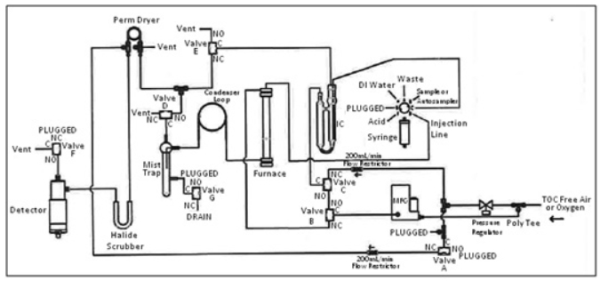
Figure 1: Torch Combustion TOC Analyzer Flow Path Diagram
The most important skill to have when looking for a hard-to-find leak is the ability to read and understand a flow path diagram. A flow diagram shows all of the valves and parts that gas can travel through along with its directionality. This directionality is controlled by solenoid valves, an example of which can be found in Figure 2. Each valve has three ports: C (Common), NC (Normally Closed), and NO (Normally Open). The C is always open. Flow normally goes from the C port to the NO port, when the valve is not actuated, and the NC port is closed. The inverse occurs when the valve is actuated, with flow going from the C port to the NC port. Figure 2 illustrates each configuration.
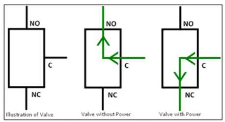
Figure 2: Illustration of Valves from Flow Diagrams
Since the flow path changes (enabled by the different solenoid valves in the pathway), depending on the step of the analysis, there are different flow diagrams for the different modes. The images below illustrate the flow path for the Furnace pathway, the IC pathway, and the shared pathway (Figures 3-5).
If a leak is found in the Furnace pathway, use the flow path diagram outlined in Figure 3. When looking for a leak, it is best to leak check manually. This is really the key to effective leak troubleshooting. In the Diagnostics menu on current Tekmar instruments, you can control which valves are given power and therefore the flow path taken. The most efficient way to find and fix a leak is to start at the beginning of the flow path, stopping at each intersection, and testing valves individually. This helps to break the instrument into simpler parts and build complexity as you add more components in the flow path. Using the following step-by-step instructions can help when manually leak checking.
Step-by-Step Leak Check Guide for Furnace Pathway on a Torch:
1. In diagnostics, make sure Valves A, B, and F are ON.
2. Insert a plug into the ‘NC’ port of Valve B
3. Set the flow to 10 mL/min (since this is so close to the MFC, it will easily over-pressure)
4. Once the flow gets to about 50psi, set the flow to 0
5. Monitor the pressure
a. After a brief stabilization, the pressure should remain stable (unless there is a leak)
6. Remove the plug from Valve B, reattach the line, and place the plug at the bottom of the furnace
7. Set the flow to 100mL/min (Can be increased if the pressure does not build quickly enough)
8. Repeat 4 – 5a
9. If a leak is found, remedy the problem by tightening or replacing fittings as needed
****Remember that it is possible to over-tighten the fittings which can lead to leak
10. Continue this process using the diagram below until the leak is found and remedied
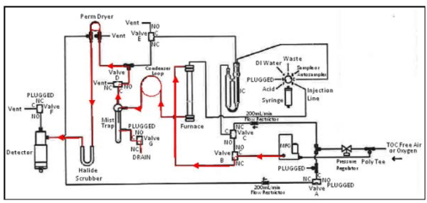
Figure 3: Furnace Pathway Flow Diagram (Valves A, B, and F are ON)
If the instrument shows a leak in both the IC path and the Furnace path, the first places to check are the shared components in the pathways as illustrated in Figure 5. However, there may be a leak in each pathway so if checking along the shared pathway does not remedy the leak, go through the IC and Furnace pathways individually.
The flow path diagram in Figure 4 would be used if the leak was in the IC Pathway. Similarly to the method used in Furnace pathway, manually leak check the system until the leak is found and fixed. The method of determining the leak location is the same, it just applies to a different set of valves.
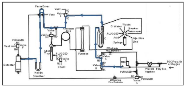
Figure 4: IC Pathway Flow Diagram (Valves A, D, E, and F are ON)
If the instrument shows a leak in both the IC path and the Furnace path, the first places to check are the shared components in the pathways as illustrated in Figure 5. However, there may be a leak in each pathway so if checking along the shared pathway does not remedy the leak, go through the IC and Furnace pathways individually.
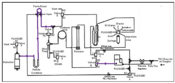
Figure 5: IC and Furnace Shared Pathway
Although these tips apply specifically to TOC analyzers, the same technique can be used to troubleshoot a variety of instruments that employ solenoid valves. Using the flow path diagrams and progressing through the system by plugging off each valve individually will help to isolate the leak. The normal troubleshooting rules still apply: be patient, work methodically, and use your references (manual, flow diagrams) to resolve the issue and get things back up and running quickly.